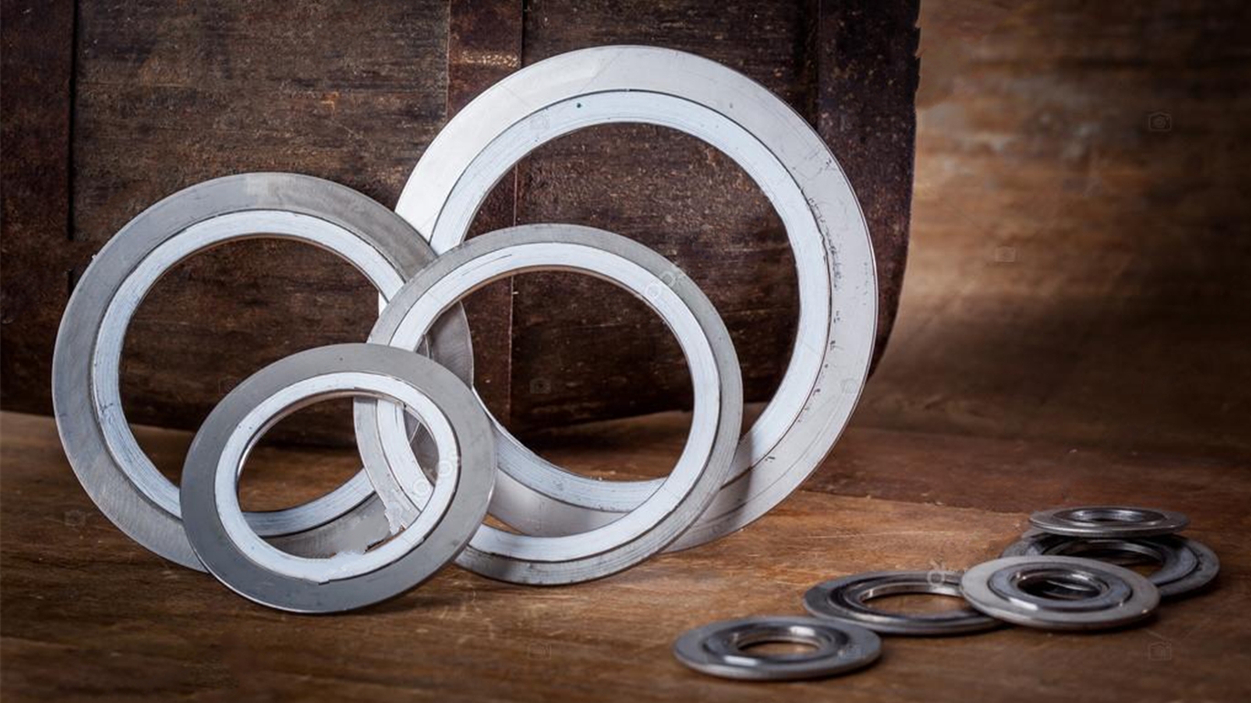

What is a steel flange
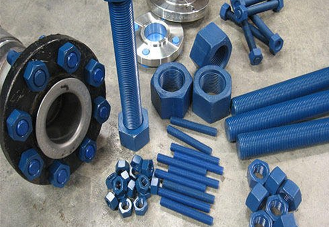
Flange is a method of connecting pipes, valves, pumps and other equipment to form a piping system. It also provides easy access for cleaning, inspection or modification.
Flanges are usually welded or bolted. Flange joints are made by bolting two flanges together with a spacer between them to create a sealing ring.

SAIGON KINHBAC (SKB). Chúng tôi cung cấp các sản phẩm phục vụ cho ngành công nghiệp. Thép công nghiệp, Ống Thép, Mặt bích thép, Phụ kiện đường ống, Ống nhựa & Phụ kiện, Van công nghiêp, Các loại khác…
Liên hệ báo giá sản phẩm hoặc thông tin thêm. Quý khách vui lòng liên hệ với chúng tôi theo điện thoại: (028) 66567569 - (028) 66569779 - (028) 66601010 - Mobile: 0987 672788 - 0962 168112. Email: info@skb.vn hoặc contact@skb.com.vn. Chúng tôi luôn sẵn lòng.
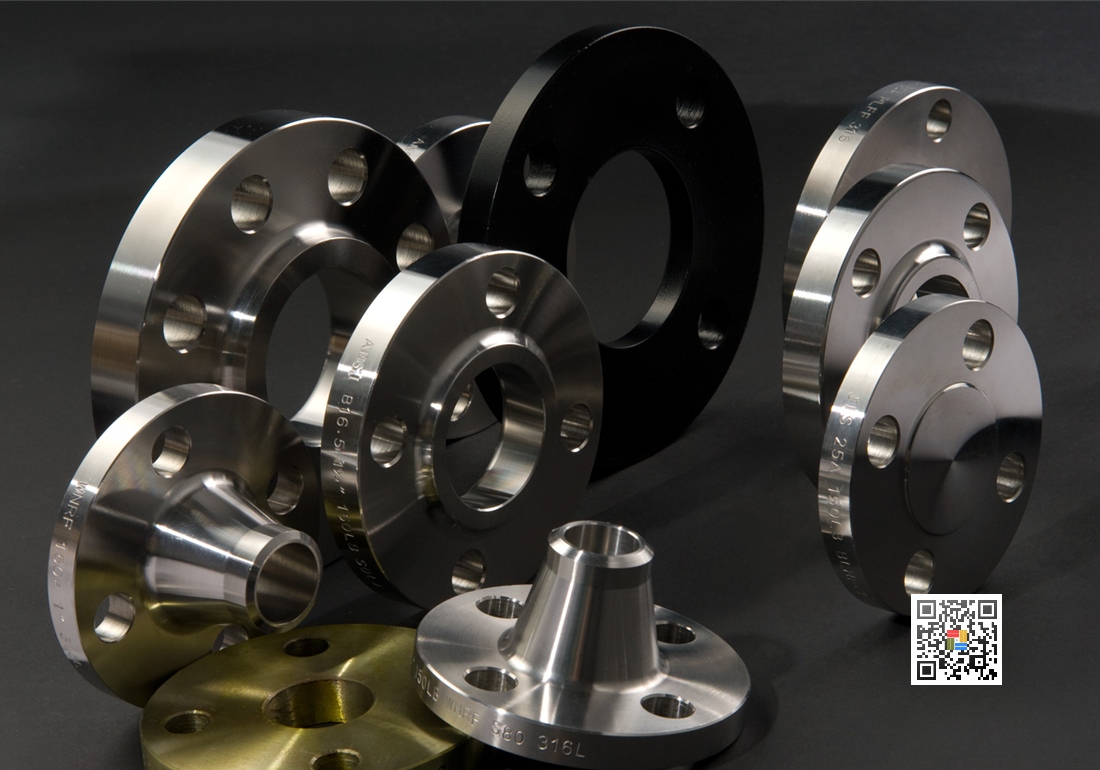
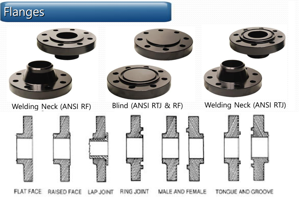
Different types of flanges are used as the contact surface for which the sealing material is placed. ASME B16.5 and B16.47 define different flange types, including raised face, male face and large female face that are identical in size to provide a relatively large contact area.
Other flanges covered by these standards include ring face large and small tongue and groove faces specifically for ring-type metal gaskets.
ASME B16.5 AND ASME B16.47 REFER TO DIFFERENT FLANGE TYPE:
-
Flat face flange (FF)
-
Raised face flange (RF)
-
Ring joint flange (RTJ)
-
Lap joint flange
-
Male and female flange (M&F)
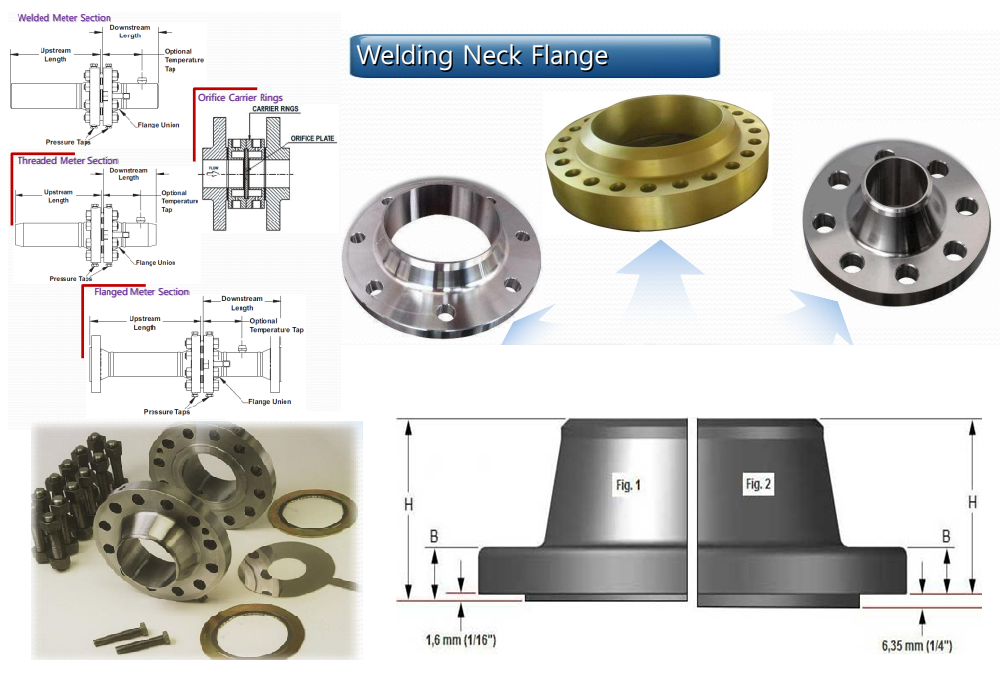
Raised face flange (RF)
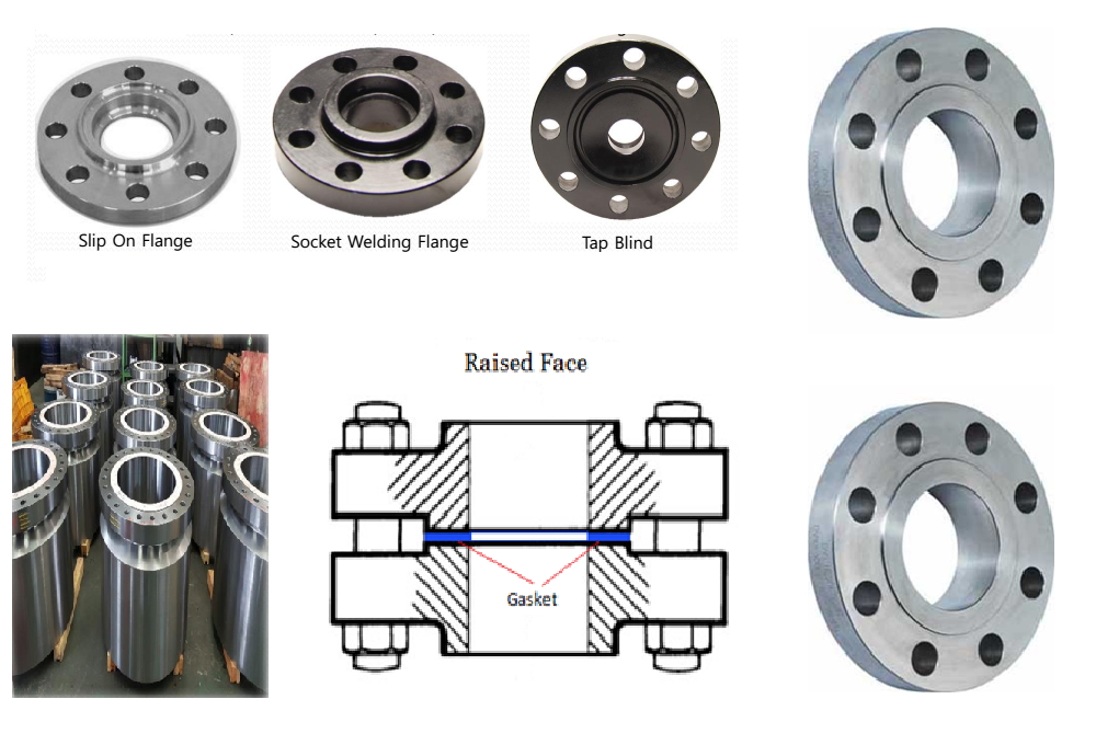
Flange Raised flanges are the most common type used in process plant applications and are easy to identify. It is called a raised face because the gasket surfaces are raised above the face of the screwed circle. This face type allows the use of a variety of gasket designs, including flat ring plate types and metal composites such as spiral wound and double jacketed types.
The purpose of RF flanges is to concentrate more pressure on a smaller gasket area and thus increase the pressure suppression ability of the joint.
Diameters and heights are defined in ASME B16.5, according to pressure class and diameter. The pressure rating of the flange determines the height of the raised face.
Typical flange finishes for ASME B16.5 RF flanges are 125 to 250 µ in Ra (3 to 6 µ m Ra).
In pressure classes 150 and 300, the height of the platform is approximately 1.6 mm (1/16 inch).
In pressure classes 400, 600, 900, 1500 and 2500, the height of the raised face is approximately 6.4 mm (1/4 inch).
Flat face flange (FF)
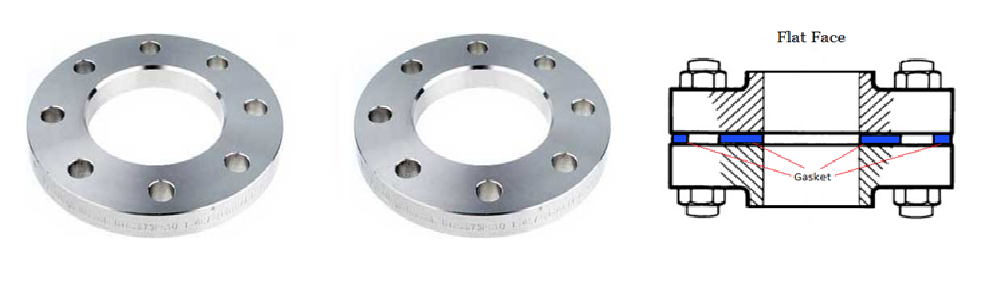
Flat Flanges have the spacer face in the same plane as the bolted ring face. Applications where flat flanges are used are typically those where the compound flange or flange fitting is made from cast material.
Flat flanges should never be bolted to raised flanges. ASME B31.1 states that when connecting a flat face cast iron flange to a carbon steel flange, the protrusion above the carbon steel flange must be eliminated and a full face gasket is required. This is to keep the thin and slightly small cast iron flanges from popping into the gap due to the raised face of the carbon steel flange.
Ring joint flange (RTJ)
Ring type joint flanges are typically used in high pressure (class 600 and above) or high temperature services above 800°F (427°C).
They have cut notches on their faces that washers are in steel. Sealing flanges when bolts are tightened compresses the gasket between the flanges into the grooves, deforming (or coining) the gasket to make intimate contact inside the grooves, creating metal for the sealing metal.
RTJ flanges are sealed with washers, the flange protrusions connected and tightened can come into contact with each other. RTJ flanges can be sealed with RTJ gaskets of different designs (R, RX, BX) and configurations (e.g. octagonal/oval for style R).
The most common RTJ gasket is the R style with an octagonal section, as it ensures a very strong seal.
Lưỡi và rãnh - Male and female flange (T&G)
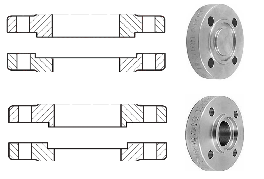
The Blade Face and Groove Face of this flange must match. A flange has a raised ring (Blade) machined on the flange while a mating flange has a suitable recess (Slot) machined into its face.
Tongue and groove faces are standardized in both large and small grades. They differ from male and female in that the inside diameter of the blade and groove do not extend into the flange base, thereby retaining the gasket on its inside and outside diameters. They are commonly found on pump covers and valve Bonnets.
Tongue-and-groove joints also have the advantage that they are self-aligning and act as an adhesive reservoir. The flange joint keeps the load shaft in line with the joint and does not require a large machining operation.
Lap joint flange
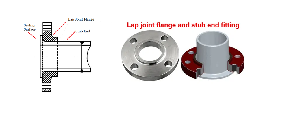
A lap joint flange has a flat face, which is not used to seal flanges but simply stores the back of a stub end. The sealing surface is actually located at the tip of the stalk and can be flat or raised.
FLANGE FACE FINISH
To ensure that a flange mates with gasket and flange companion perfectly, some roughness is required on the flange surface area (RF and FF flange finishes only). The rough pattern on the flange surface determines the flange end flange type.
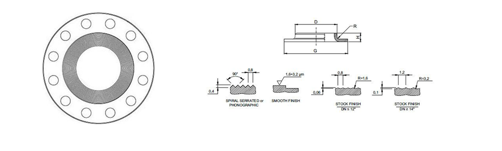
ASME code B16.5 requires flanges (lift and plane) to have a specific roughness to ensure that the surface is compatible with the gasket and provides a high quality seal.
A serrated, concentric or spiral finish is required with 30 to 55 grooves per inch and results in a roughness of 125 to 500 microinches. This allows flange manufacturers to have a variety of surface finishes for the gasket contact surfaces of metal flanges.
-
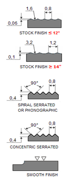
Stock Finish
-
Spiral Serrated
-
Concentric Serrated
-
Smooth Finish
Smooth Finish
Steel flanges are available in four basic finishes, however, the overall goal of any flange type is to create the desired roughness on the flange to ensure a strong joint between the flange, gasket and the flange face. distribution and thus provide a high quality seal.
Stock Finish
The finished finish is the most common finish as it is suitable for the majority of applications. Pressure dips the soft side of the gasket into the flange and leads to the formation of a good seal due to the friction that exists between the contacting parts.
When mating flanges are bolted together, the gaskets can press firmly against the flange and create a very tight seal.
A neck finish manufactured using a phonetic spiral groove has a 1.6mm radius round nose tool with a depth of 0.15mm and a feed rate of 0.8mm per revolution. The resulting Ra (AARH) value for the surface ranges from 125µinch to 500µinch (125 µm to 12.5 µm).
Serirated spiral
The spiral serrated finish is a phonetically helical type of groove that round from the stock finish because the groove is made with a 90 degree tool (instead of a geometry) creating a “V” with a 45-degree geometry.
A concentric or spiral serrated finish with 30 to 55 grooves per inch and a roughness between 125 and 250 inches
Concentric serrated
Concentric serrated flanges have concentric grooves instead of spirals.
The grooves are made with the same 90 degree tool used for the helical serration finishing, but the serrations have a uniform design across the face of the flange. For concentric grooves, the tool has a feed rate of 0.039mm per revolution and a depth of 0.079mm.
Smooth finish
Flanges with a smooth finish do not show visible tool marks to the naked eye.
This type of flange finish is used with metal face gaskets as the jacket type.
According to stock finishes, this is achieved by machining the contact surface with the continuous spiral groove produced by the 0.8mm radius round nose tool at a feed rate of 0.3mm per revolution with a 0.05mm deep (create a roughness between Ra 3.2 and 6.3 microinches ie 125 - 250 microinches).
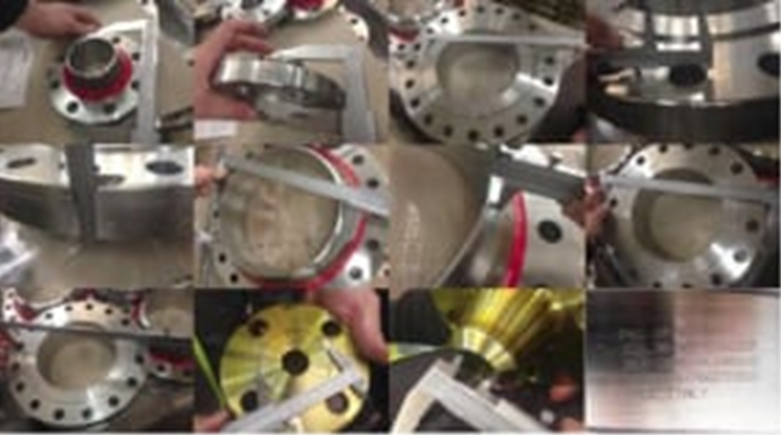
CHECK FLANGE PARAMETERS
Outside & inside diameter of flange
Bolt Circle & Bolt Hole Diameter
Hub diameter & weld thickness
Length of Center Flange
Bolt Hole Straightness and Alignment
Marking
The following information will be printed on the body of the flange:
Manufacturer logo (Manufacturer logo)
Material code (ASTM/BS/JIS/DIN material code)
Material Grade
Service level – Service rating (Pressure-temperature Class))
Size
Thickness (Schedule)
Production batch – Heat No.
Special marking if any QT (Quenched and tempered) or W (Repair by welding)
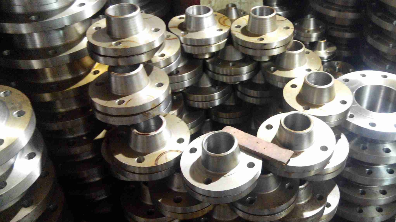
+1000 Products catalog
Quality products approved from factory, competitive price. Arrange delivery in a short time, helping you to reduce time and save costs.
Tag bích thép